FLAMELESS GASIFICATION TECHNOLOGY FOR COAL PROCESSING (TERMOLYSIS)
Brief Introduction to Flameless Gasification Technology (Thermolysis Method)FLAMELESS GASIFICATION COMPLEX
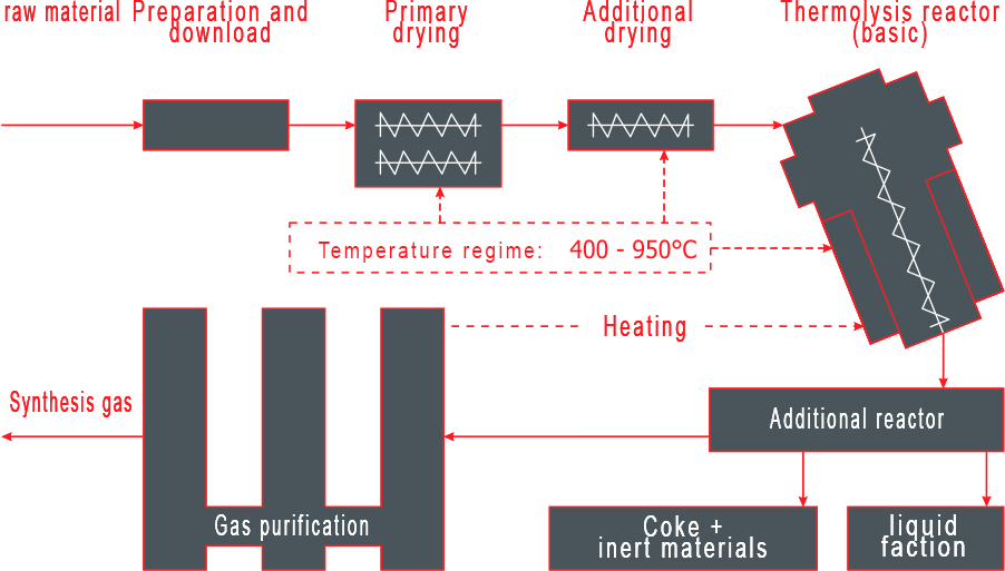
Main blocks of thermolysis equipment, 6 - gas production and purification, 7 - purified synthesis gas, 8 - water purification, 9 - storage gas, 10 - reactors of the second level, 11 - inert materials")
1 - raw materials, 2 - preparation and loading, 3 - primary drying, 4 - additional drying, 5 - thermolysis reactors (main), 6 - gas production and purification, 7 - purified synthesis gas, 8 - water purification, 9 - storage gas, 10 - reactors of the second level, 11 - inert materials

RAW MATERIAL PREPARATION UNIT
( optional)
for the selection of the mineral component and moisture from raw materials, reducing the sulfur content in the raw materials and crushing the raw materials to the dimensions required for the technological process (no more than 150 mm on the largest side)

CHEMICAL OR FUEL OUTLET UNIT
( optional)
for the production of a variety of chemical products or automotive fuel from synthesis gas in accordance with the customer's specifications

ENERGY RESOURCES GENERATION
(optional)
for the production of electrical and thermal energy from synthesis gas and coke produced from raw materials using the technology of their flameless gasification in accordance with the customer's specifications

BLOCK FOR SELECTING METALS OF DIFFERENT GROUPS
( optional)
for the production of electrical and thermal energy from synthesis gas and coke produced from raw materials using the technology of their flameless gasification in accordance with the customer's specifications
DESCRIPTION OF THE PROCESS (thermolysis)
The production process of processing organic raw materials in the form of coal, peat or oil shale (hereinafter referred to as raw materials) using thermolysis technology looks as follows.Raw materials arriving for processing (if necessary, it goes through the enrichment and grinding stage at the raw material preparation unit) are stored. From the warehouse, raw materials are formed into loading batches, and then fed through augers from the loading hopper to the gasification unit. The incoming raw materials (due to their direct and indirect heating with the help of the produced synthesis gas) rise in their temperature, additional evaporation of water residues occurs and oxygen is separated.
The dried raw materials are fed through the apparatus through the screws to the multistage thermolysis reactor for its flameless gasification at temperatures from 400 ° C to 950 ° C. Each thermolysis reactor consists of two gasification chambers. In the course of the flameless gasification reaction, synthesis gas is formed, which then enters the gas enrichment section, where it is purified from harmful impurities and by-products. Semi-coking and fumigation of raw materials occurs in both gasification chambers at different temperatures. Heating required for the coking process is carried out using heating pads on the outer shell of the thermolysis reactor.
Monitoring the operation of gasification reactors and a guarantee of their safe operation are realized with the help of a number of measuring probes and a safety system concentrated in a single dispatching system. The gas pipeline system is protected from overpressure by the presence of the correct number of test diaphragms. In the event of an increase in internal pressure or in case of an emergency, the resulting gas is diverted to the torch. Additionally, there is a system for providing water and steam to instantly stop the gasification reaction.
A cascade of two sequential coking units is connected to the gasification reactors. They undergo further thermal decomposition of the feedstock together with the primary coke oven material for the extraction of synthesis gas. Like the thermolysis reactor, the coking units are equipped with a heating jacket for direct heating. The resulting solid residue in the form of coke, which, after appropriate cooling with steam and water, is transferred to closed containers. In the enrichment section, the synthesis gas passes through a system of scrubbers, separators, tanks and pumps. A scrubber (gas absorption unit) is connected to each reactor. After them, the gas streams of both lines are connected and directed through the cascades of absorption cleaning, which, during their circulation, absorb condensate from the coking gas, while simultaneously cooling it.
With thermolysis technology, organic substances decompose into short-chain hydrocarbons, and metal oxides, like oxides of other inorganic substances (for example, sulfur oxide compounds), are reduced.
When cleaning synthesis gas, complete condensation of aliphatic and aromatic substances is achieved. The content of harmful impurities (eg HCL) is reduced by neutralization with lime water, in compliance with the prescribed requirements.
The exhaust air from the thermolysis process enters the biological purification of the exhaust air. To eliminate the emission of off-gas odors accompanying the sewage treatment and multi-stage drying of raw materials, they are removed from the working areas through a pipeline system with integrated biological gaskets.
The process gas stream, after passing through all the cleaning processes, enters the gas storage. The gas storage is used to receive and buffer the synthesis gas obtained in the thermolysis process, to provide power to the reactors and coking units, and is also intended to remove gas to the consumer using a compressor station. By back mixing the produced gas, its quality from the reactor lines is equalized.
The resulting synthesis gas is supplied at the request of the customer with the use of additional equipment, optionally either for the generation of energy resources, or for the production of various chemical products.
The protective system consists of a torch, which, in the event of an emergency, serves as a reliable drainage of synthesis gas from the coking plant or from the gas storage. The connecting pipelines are equipped with fittings that open autonomously when the power supply is cut off. Flare gasification reactors are equipped with safety membranes to prevent emergency pressure build-up.
Waste water from water treatment systems is used to power the plants, which is then returned back. Organic residues are periodically withdrawn and loaded into the thermolysis unit. The water circulation system for cleaning the process gas contains cooling units, which are connected in the circulation water supply circuit with a heat carrier operating in ambient air.
STAGES OF COAL AND OIL SHALE PROCESSING USING FLAMELESS GASIFICATION TECHNOLOGY (TERMOLYSIS)
Raw material processing stage
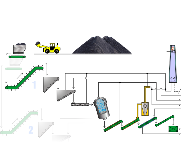
Flameless gasification unit line 1 and line 2
The raw material that has passed the stage of sorting and grinding to the required parameters is transferred from the industrial site to the flameless gasification unit for the production of synthesis gas.
Supply of prepared raw materials to the gasification unit
Sorted and prepared wastes from the warehouse at the industrial site are formed into loading batches and fed to the flameless gasification unit.
Main reactor and reactor of the second level
Separation unit
In the separation unit connected to the flameless gasification reactors, the generated synthesis gas is purified from fine mineral particles and dust
Safety unit
Control over the operation of thermolysis reactors and a guarantee of their safe operation are realized with the help of a number of measuring probes and a safety system concentrated into a single dispatching system.
Synthesis gas purification stage
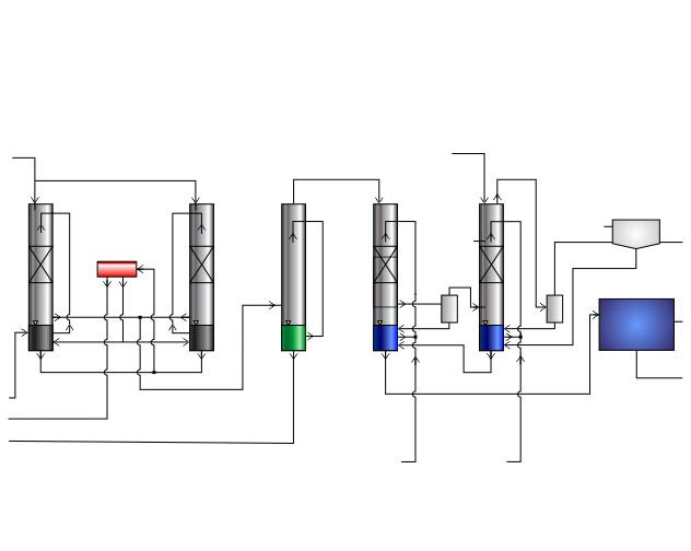
1 stage of synthesis gas purification
In the beneficiation section, the generated synthesis gas passes through a system of scrubbers, separators, tanks and pumps. A scrubber (gas absorption unit) is connected to each reactor.
Stage 2 of synthesis gas purification
At the second stage of synthesis gas purification, the primary reduction of the content of harmful impurities (for example, HCL) occurs in it due to neutralization with lime water, in compliance with the prescribed requirements.
3 stage of synthesis gas purification
At the third stage, the final purification of synthesis gas from harmful impurities takes place.
4 stage synthesis gas purification
At the fourth stage of the synthesis gas purification, complete condensation of aliphatic and aromatic substances is achieved. During the last cycle, harmful substances and light particles are removed in a state associated with the working environment.
Water and exhaust air purification stage
Liquid fraction separator, water treatment
Oil-containing working medium and water after flameless gasification reactors are separated by oil separators.
Water purification
In the water treatment unit, the waste water present in the technological process after the thermolysis reactors is additionally purified with activated carbon and biological treatment of waste water. Thereafter, the wastewater can be discharged to the wastewater disposal system of industrial areas.
Water purification, air stripper
The air stripper unit is used for biological purification of exhaust air during the thermolysis process, as well as for eliminating odor emissions associated with wastewater treatment.
Comparison of characteristics of technologies for processing oil shale
Table 1
| Technology name | |||||
|---|---|---|---|---|---|
| FUSHUN | Kiviter | Galoter (Enefit140, Petroter) |
PETROSIX | THERMOTEC | |
| A country | China | Estonia | Estonia | Brazil | Germany |
| Company | various | EESTI ENERGIA, VКG | EESTI ENERGIA, VКG | THERMOTEC POWER | |
| Retort type | vertical | vertical | horizontal | vertical | oblique |
| Oil shale processing volume, tons / day | 100 | 1,000 | 3,000 | 6 200 and 1 600 | block one 520 |
| Fraction size, mm | 10 - 75 | 25 - 125 | 0 - 25 | 6 - 50 | 0 - 125 |
| Resin yield according to Fischer-Tropsch,% | 65 | 75 - 80 | 73 - 78 | 85 - 90 | - |
| Carbon content in ash,% | N. D. | 8.0 | 1.5 | N. D. | 0.01 |
| Moisture content in ash,% | N. D. | 30.0 | 15.0 | N. D. | 1.0 - 3.0 |
Source: literature review
Comparison of indicators for the implementation of various technologies for processing oil shale
Table 2
| FUSHUN | Galoter (Enefit140, Petroter) |
THERMOTEC | |
|---|---|---|---|
| Type of equipment | FUSHUN | UTT 3000 | THERMO 190 |
| Company | SINOPEC | EESTI ENERGIA, VКG | THERMOTEC POWER |
| Oil shale processing volume, tons / day | 3,000 * | 3,000 * | 3,000 * |
| The size of the fraction of oil shale for processing, mm | 10 - 75 | 0 - 25 | 0 - 125 |
|
Production of marketable products: |
|
|
|
Source: literature review
* with power plant efficiency of 0.40 and Estonian oil shale processing