TECHNOLOGY OF PROCESSING OF MUNICIPAL WASTE
Brief description of the process of flameless gasification of the generated municipal waste on the equipment of the complexComposition of the flameless gasification complex
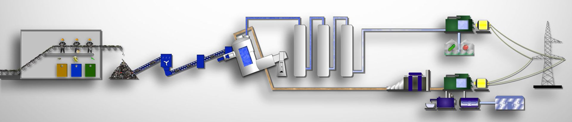
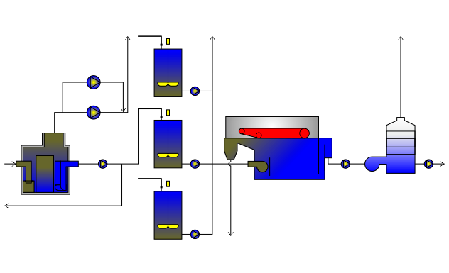
The complex for flameless gasification of generated municipal waste will include the following main blocks:-
Loading material selection unit -
for sorting incoming waste (selection of stones and sand, scrap metal, glass and food waste with biomass) -
Flameless Gasification Unit -
for the production of syngas and coke -
Biogas unit -
for processing food waste and biomass
Unit for selection of generated municipal waste
The selection unit is designed for sorting and crushing the generated municipal waste in order to prepare it for flameless gasification modules, sampling food waste and plant mass for a biological gas unit with power equipment, as well as selecting secondary raw materials in the form of scrap ferrous and non-ferrous metals, glass for their subsequent implementation to the side. At the same time, screening of inert materials such as sand, stones and construction waste will be carried out.Biological gas unit with power equipment
The sorted part of raw materials, in the form of food waste and biomass, has its own characteristics, therefore, for their processing, an additional preliminary preparation area is required (grinding, separation of inorganic inclusions and pasteurization).The accumulation of a similar part of the prepared raw material is designed for 1-2 days and takes place in the receiving tank. After the receiving tank, food waste is pumped into the reactor, which is kept for 8 to 10 days. There, special temperature conditions are created from + 25 ° C to + 28 ° C in compliance with the humidity corresponding to the technological process with control of the pH level. From the reactor there is a dosed supply of raw materials to the biological unit to maintain the bacterial balance in the biological substrate. The spent biological substrate is loaded and unloaded automatically.
After unloading, the biological substrate is separated into solid biological fertilizers and liquid biological fertilizers. The resulting biological gas is collected in external gasholders and used to generate the electrical and thermal energy required for the complex.
Biogas is discharged through a pipeline, which is equipped with automatic condensate drainage devices and safety devices that protect the gas tank from exceeding the permissible pressure.
From the gasholder, biological gas is continuously fed to a gas piston unit to generate electricity and heat. The operation of the entire biological gas unit with power equipment is controlled by commands from the central software module.
Unit for flameless gasification of prepared waste (thermolysis)
The production process of utilization of the generated municipal waste using the thermolysis technology is as follows.
Received for processing, prepared and sorted solid household waste (without food waste and biomass, as well as without inert materials), are stored. From the warehouse, they are formed into loading batches and fed to the gasification unit. The incoming waste (due to direct and indirect heating with the help of the produced synthesis gas) increases in temperature, water evaporates and oxygen is separated. The dried waste is fed through the apparatuses through the screws to the multistage thermolysis reactor for its flameless gasification at temperatures from 400 ° C to 950 ° C. Each thermolysis reactor consists of two gasification chambers. In the course of the flameless gasification reaction, synthesis gas is formed, which then enters the gas enrichment section, where it is purified from harmful impurities and by-products. Semi-coking and fumigation of municipal solid waste occurs in both gasification chambers at different temperatures. Heating required for the coking process is carried out using heating pads in the combustion chambers on the outer shell of the thermolysis reactor.
Monitoring the operation of gasification reactors and a guarantee of their safe operation are realized with the help of a number of measuring probes and a safety system concentrated in a single dispatching system. The gas pipeline system is protected from overpressure by the presence of the correct number of test diaphragms. In the event of an increase in internal pressure or in case of an emergency, the resulting gas is diverted to the torch. Additionally, there is a system for providing water and steam to instantly stop the gasification reaction.
A cascade of two sequential coking units is connected to the gasification reactors. They undergo further thermal decomposition of household waste together with the primary coke oven material for the extraction of synthesis gas. Like the thermolysis reactor, the coking units are equipped with a heating jacket for direct heating. The resulting solid residue in the form of coke, which, after appropriate cooling with steam and water, is transferred to closed containers. In the enrichment section, the synthesis gas passes through a system of scrubbers, separators, tanks and pumps. A scrubber (gas absorption unit) is connected to each reactor. After them, the gas streams of both lines are connected and directed through the cascades of absorption cleaning, which, during their circulation, absorb condensate from the coking gas, while simultaneously cooling it. With thermolysis technology, organic substances decompose into short-chain hydrocarbons, and metal oxides, like oxides of other inorganic substances (for example, sulfur oxide compounds), are reduced. When cleaning synthesis gas, complete condensation of aliphatic and aromatic substances is achieved. The content of harmful impurities (eg HCL) is reduced by neutralization with lime water, in compliance with the prescribed requirements. The oily working medium and water are separated by oil separators. Wastewater is additionally treated with activated carbon and biological wastewater treatment by a thermolysis unit. After that, the waste water can be discharged into the waste water disposal system of industrial and production areas. The exhaust air from the thermolysis process enters the biological purification of the exhaust air. To eliminate the emission of off-gas odors associated with wastewater treatment and multi-stage waste drying, they are removed from the working areas through a pipeline system with integrated biological gaskets.
The process gas stream, after passing through all the cleaning processes, enters the gas storage. The gas storage is used to receive and buffer the synthesis gas obtained in the thermolysis process, to provide power to the reactors and coking units, and is also intended to remove gas to the consumer using a compressor station. By back mixing the produced gas, its quality from the reactor lines is equalized. The resulting synthesis gas is supplied at the request of the customer with the use of additional equipment, optionally either for the generation of energy resources, or for the production of various chemical products.
The protective system consists of a torch, which, in the event of an emergency, serves as a reliable drainage of synthesis gas from the coking plant or from the gas storage. The connecting pipelines are equipped with fittings that open autonomously when the power supply is cut off. Flare gasification reactors are equipped with safety membranes to prevent emergency pressure build-up.
Waste water from water treatment systems is used to power the plants, which is then returned back. Organic residues are periodically withdrawn and loaded into the thermolysis unit. The water circulation system for cleaning the process gas contains cooling units, which are connected in the circulation water supply circuit with
Flameless waste gasification process flow diagrams
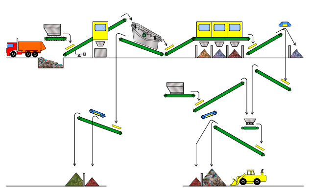
Waste sorting stage
Sorting station
designed for pre-selection of generated municipal waste in order to select food waste and biomass, metal and glass, stones, ceramics, sand and household construction waste.
Incoming waste
The generated municipal waste is temporarily stored at the site in front of the sorting station.
Loading
Large items (sofas, wardrobes, TVs, computer monitors, etc.) are selected separately with one loader. Another loader carries out constant loading of household waste into the storage hopper for feeding to the sorting station.
Vibrating sieve
The elevator conveyor transports the waste from the storage hopper to the distributor conveyor, from which this prepared waste goes to the washer and vibrating sieve for sifting fine material (sand, stones, ceramics and small household construction waste).
Manual sorting station (1)
Material from the vibrating sieve goes to the sorting conveyor located in the closed cabin of the sorting station for the selection of food waste and biomass, glass, metal residues after they are collected before being fed to the sorting station.
Manual sorting station (2)
>Recyclable materials sorted on a conveyor, in the form of glass and metal residues, as well as food waste and biomass, are sent at each workplace to the mines for material disposal.
Magnets
After manual preliminary sorting of the waste in a closed cabin, the input raw material is directed through a series of magnets to catch the remaining scrap of ferrous and non-ferrous metals.
Processing of metals
The collected secondary raw materials in the form of scrap ferrous and non-ferrous metals are subject to pressing and packaging.
Shredder
After the selection of ferrous scrap, the input raw materials are conveyed to the shredder through the conveyor, in order to crush the waste that has passed the screening stage to the required parameters, for further delivery to the flameless gasification reactors.
The final stage of sorting
Prepared and sorted household waste is stored on an industrial concrete site adapted for this purpose for its subsequent supply to the flameless gasification unit.
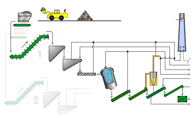
Raw material processing stage
Flameless gasification unit line 1 and line 2 Having passed the stage of sorting and grinding to the required parameters, the raw material is supplied from the industrial site to the flameless gasification unit to generate synthesis gas.
Supply of prepared raw materials to the gasification unit Sorted and prepared waste from the warehouse at the industrial site is formed into batches and fed to the flameless gasification unit
Main Reactor and Second Level Reactor
Separation unit
In the separation unit attached to the flameless gasification reactors, the generated synthesis gas is purified from fine mineral particles and dust
Safety unit
Control over the operation of thermolysis reactors and a guarantee of their safe operation are realized with the help of a number of measuring probes and a safety system concentrated into a single dispatching system.
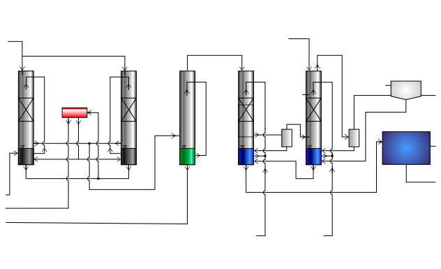
Synthesis gas purification stage
1 stage of synthesis gas purification
In the beneficiation section, the generated synthesis gas passes through a system of scrubbers, separators, tanks and pumps. A scrubber (gas absorption unit) is connected to each reactor.
2nd stage of synthesis gas cleaning
At the second stage of synthesis gas purification, the primary reduction of the content of harmful impurities in it (for example, HCL) occurs due to neutralization with lime water, in compliance with the prescribed requirements.
3 stage of synthesis gas purification
At the third stage, the final purification of synthesis gas from harmful impurities takes place.
4 stage synthesis gas purification
At the fourth stage of the synthesis gas purification, complete condensation of aliphatic and aromatic substances is achieved. During the last cycle, harmful substances and light particles are removed in a state associated with the working environment.
Purification of water and exhaust air
Liquid fraction separator, water treatment
Oil-containing working medium and water after flameless gasification reactors are separated by oil separators.
Water purification
In the water treatment unit, the waste water present in the technological process after the thermolysis reactors is additionally purified with activated carbon and biological treatment of waste water. Thereafter, the wastewater can be discharged to the wastewater disposal system of industrial areas.
Water purification, air stripper
The air stripper unit is used for biological purification of exhaust air during the thermolysis process, as well as for eliminating odor emissions associated with wastewater treatment.
Comparative indicators of various technologies for utilization and processing of generated municipal waste
| # | Indicators | Measurement units |
Technology | ||||
|---|---|---|---|---|---|---|---|
| Thermal processing | Plasma | Flameless gasification (thermolysis) |
Composting (biological gasification) |
||||
| * Burning |
** Pyrolysis |
||||||
| 1 | Specific operating costs |
EUR / 1t of solid waste | 34-45 | 30-35 | 45-57 | 45-55 | 27-32 |
| 2 | Specific environmental payments | EUR / 1t of solid waste | 2 | 2 | one | not | 2 |
| 3 | Specific income of the enterprise | EUR / 1t of solid waste | 20 | 17 | five | 90-200 | five |
| 4 | Specific energy costs | KW / 1t solid waste | 50 - 70 | 50 - 70 | 500 | 65 | 90-120 |
| 5 | Specific occupied area | m² / 1t of solid waste per year | 0.1-0.2 | 0.15-0.30 | 0.1-0.2 | 0.1 | 0.4-0.6 |
| Environmental aspects | |||||||
| 6 | Production waste | % of the mass of solid waste | 23 - 28 (ash and slag) | 25 -30 (coke residue) | Finely dispersed dust, heavy metal fumes |
sand and stones from sorting, no ash and slag | 20 - 25 (non-compostable fractions) |
| 7 | Soil pollution | only the presence of a slag dump | coke residue only | Hardly ever | not | Hardly ever | |
| 8 | Groundwater pollution | not | not | not | not | not | |
| 9 | Air pollution | within norms | within norms | heavy metals | not | within norms | |
| Received products of solid waste processing | |||||||
| 10 | Energy of produced steam *** | MW / 1 t of solid waste | 160 | 120 | not | not | not |
| 11 | Electricity | MW / 1 t of solid waste | 0.40 | 0.30 | 0.50 | 1.5-2.5 | not |
| 12 | Compost | % of the mass of solid waste | not | not | not | not | 50 |
| 13 | Black metal | - "- | 2 | 2 | 3 | 3 | 3 |
| 14 | Non-ferrous metal | - "- | - | 0.3-0.4 | - | 0.3-0.4 | 0.3 -0.4 |
| 15 | Other recyclable materials | - "- | - | 5 -10 | 15 - 20 | Cullet 3-6 | 5-10 |
* The combustion technology is considered on the example of using combustion devices with grate grates.
** As a pyrolysis technology, a system with a pyrolytic reactor operating at an average temperature of 850 ° C is considered.
*** Produced water vapor is used for electricity generation (own and external consumption), technological needs and plant's own needs (heating, ventilation, hot water supply)
Comparison of technologies: on the example of an operating waste incineration plant in Baku , a plant project in Buryatia, and a project for a flameless waste gasification plant
table 2
| Index | unit of measurement | * 4th generation waste incineration plant in Baku . Built by the French company "CNIM SA" | Implementation project of the THERMOTEC POWER flameless gasification complex in the RF | Mitsubishi Heavy Industries Ltd plant project in Buryatia |
|---|---|---|---|---|
| Waste processing capacity per year | Tons | 500,000 | 240,000 | 240,000 |
| Electricity generation | MWh | 28 | 25 | 10.2 |
| The use of natural gas in the production process | Well no | Yes | Not | Yes |
| Burial remains | Well no | Yes | Not | Yes |
| Number of new jobs created | Man | 100 | 100 | 100 |
| Approximate footprint | Ha | 20 | 4.5 | 7.0 |
* Link to publication on the Internet (source of the cited data): http://vesti.az/news/119327
Comparison of the technology of incineration of municipal and industrial waste with the technology of flameless gasification indicates in favor of the latter.